d-touch Markers
I’ve been using something called d-touch recently, which could be described roughly as “barcodes that can look interesting”, and it doesn’t require expensive or specialist equipment, just a webcam and a capable CPU.
A program running on the computer monitors the feed from the webcam, and when it sees one or more of the “markers”, it can be instructed to respond appropriately.
As I attempted to explain in a presentation recently using this wonderful animation, blown up to huge proportions by projector, the markers are identified using their region adjacency graphs.

So unlike barcodes, they can be made to look super interesting.
However, when you need a couple of hundred such markers, coming up with images (which quite honestly is hard enough on its own given the requirements) that each have a unique graph, can get a bit tedious if not impossible.
Luckily, d-touch has some clever stuff built into it, where as long as the marker has a single empty white region and the remaining white regions are sensibly laid out, the graphs don’t actually have to be unique. If the same graph is defined in the configuration multiple times, d-touch will start at that empty white region, or at the lowest valued (on how many regions it contains) white region, and select the next region as the one with the closest central point to that first region. So in other words, the position of regions can become relevant.
One of the applications on the d-touch site comes with 24 markers, all based on permutations of the 1,2,3,4 graph.
I’ve taken that design, and extended it in order to create a bigger set of markers.
After some sketching and calculating, I wrote the following Perl script to do the hard work for me. It generates the images, saves them to a folder, and generates the sequence file for use with the DTServer application.
#!/usr/bin/perl
use POSIX;
use GD;
use Algorithm::Permute;
use File::Util 'SL';
use File::Path 'make_path';

## d-touch marker generator
## zoril.co.uk
## 02/Nov/2011

## only generates markers based on distance
## : 0,1,2,3,4 / 0,1,3,4,2
## not based on repeated numbers
## : 0,1,1,3,4 / 0,2,1,3,2


## Number of Regions
## zero based (i.e. don't count the first zero white region).

#my $regions=2;  ##  3 regions, 2! unique markers
#my $regions=3;  ##  4 regions, 3! unique markers
#my $regions=4;  ##  5 regions, 4! unique markers
#my $regions=5;  ##  6 regions, 5! unique markers
my $regions=6;  ##  7 regions, 6! unique markers
#my $regions=7;  ##  8 regions, 7! unique markers
#my $regions=8;  ##  9 regions, 8! unique markers
#my $regions=9;  ## 10 regions, 9! unique markers
## ...
#my $regions=25; ## 26 regions, 25! unique markers, with very small dots.

## don't go over 25 without modifying @grid and @dimensions


## keeping 'space' about an 8th the size of 'size'
## seems a fairly good match.
## Sizes are in pixels.

my $space = 8; # gaps between regions
my $whitesquare = 40; # size of white regions
my $pad = 5; # gaps between black regions


## where to save images
my $outputdir = '.'.File::Util->SL.'markers'.File::Util->SL;

## seq.txt will save to current dir


## this sets up the inner dot grid
## so 25 regions, results in a 5x5 grid of small dots
## where 9 results in a 3x3 grid of bigger dots
my $dotgridsize = 0;
while($dotgridsize*$dotgridsize < $regions) { $dotgridsize++; } ## find width of dot (whiteregion - spacing) / numdots my $dotsquare = floor(($whitesquare-($dotgridsize+1)*$pad)/$dotgridsize); ## try to distribute spare pixels my $initdotpadding = floor(($whitesquare - (($dotgridsize+1)*$pad + $dotgridsize*$dotsquare)) / 2); ## fix off by one on the black regions $dotsquare--; ## make output dir make_path($outputdir); ## this sets where the regions are located ## and the order in which they are used ## Important: list in order of distance from top left. ## to withstand skew, the distances need to be carefully considered ## selecting both 3.00 and 3.16 would probably be a poor choice as they ## are very close, however they are close on the image and perhaps the ## skew would be less between them than between other less numerically ## close regions ## Select any of the following pre-contained regions, then list the ## x,y coordinates: @grid = ( "0,0", "0,1", "1,1", "0,2", "1,2" ); ## Ensure they are listed in increasing order. ## It may not make a square marker but it will give them correct filenames. ## ..and for python: def s(x,y):return (x**2+y**2)**.5 ############################################ ####### 0 # 1 # 2 # 3 # 4 # 5 ## ############################################ ## 0 ## 0.00 1.00 2.00 3.00 4.00 5.00 ## 1 ## 1.00 1.41 2.24 3.16 4.12 5.10 ## 2 ## 2.00 2.24 2.83 3.61 4.47 5.39 ## 3 ## 3.00 3.16 3.61 4.24 5.00 5.83 ## 4 ## 4.00 4.12 4.47 5.00 5.66 6.40 ## 5 ## 5.00 5.10 5.39 5.83 6.40 7.07 my @grid = ( "0,0", "0,1", "1,1", "0,2", "1,2", "2,2", "3,2", "4,0", "4,2" ); ## similar to above, but defines how many regions wide,high the image ## should be when the marker contains up to that many regions ## for above example: @dimensions = ( "1,1", "1,2", "2,2", "2,3", "2,3" ); my @dimensions = ( "1,1", "1,2", "2,2", "2,3", "2,3", "3,3", "4,3", "5,3", "5,3" ); my ($horiz, $vert) = split(/,/, $dimensions[$regions]); my $width = $space + $horiz*$whitesquare + $horiz*$space; my $height = $space + $vert*$whitesquare + $vert*$space; ## get number range my @array = (1..$regions); my $permuter = Algorithm::Permute->new( \@array );

## create image
my $im = newTrueColor GD::Image($width,$height);

## set up colours
my $cb  = $im->colorAllocate(0,0,0);
my $cw  = $im->colorAllocate(255,255,255);

## main black region
$im->filledRectangle(0,0,$width,$height,$cb);

## create seq file
open(TXT,">seq.txt") or die $!;

## for every possible order
while (my @perm = $permuter->next) {
    $gridref = 0;
    ## make some white regions
    for($m = 0; $m <= $regions; $m++) { ## in these places ($x, $y) = split(/,/, $grid[$m]); my $startx = $space + (($space+1)*$x) + (($whitesquare-1)*$x); my $starty = $space + (($space+1)*$y) + (($whitesquare-1)*$y); my $endx = $startx + $whitesquare - 1; my $endy = $starty + $whitesquare - 1; ## draw $im->filledRectangle($startx,$starty,$endx,$endy,$cw);

        my $dotsrequired = 0;
        my $dots = 0;

        ## ignore the zero region or get the dot count
        if($gridref > 0) { $dotsrequired = @perm[$gridref-1];}

        ## draw inner black regions
        ## keep adding dots up to max/until reached goal
        for(my $ax = 0; $ax < $dotgridsize; $ax++) { if($dots >= $dotsrequired) { last; } ## stop wasted looping
            for(my $ay = 0; $ay < $dotgridsize; $ay++) { if($dots >= $dotsrequired) { last; } ## break loop if enough regions

                $dots++;

                ## shift to white region and position inner dots
                my $dotstartx = $startx + $initdotpadding + $pad + (($pad+1)*$ax) + ($dotsquare*$ax);
                my $dotstarty = $starty + $initdotpadding + $pad + (($pad+1)*$ay) + ($dotsquare*$ay);
                my $dotendx = $dotsquare + $dotstartx;
                my $dotendy = $dotsquare + $dotstarty;

                ## draw
                $im->filledRectangle($dotstartx,$dotstarty,$dotendx,$dotendy,$cb);
            }
        }
        $gridref++;
    }
    ## comma seperated
    $" = ",";
    print "permutation: (@perm)\n";
    ## write to seq file
    print TXT "0,@perm\n";
    ## write image
    $" = "-";
    open(IMG,">${outputdir}image_0-@perm.png") or die $!;
        binmode IMG;
        print IMG $im->png;
    close IMG;
}
close TXT;
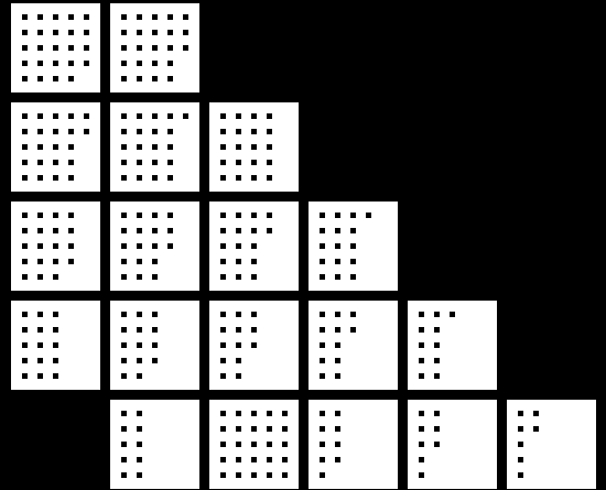
As you may have noticed, this goes up to 26 region markers, which gives 25! (factorial) unique markers. 25 factorial, thanks to Wolfram Alpha, is apparently 15 septillion, 511 sextillion, 210 quintillion, 43 quadrillion, 330 trillion, 985 billion, 984 million ..I think that counts as an unnecessarily large number of markers. Of course at that number of leaf-level regions, it probably wouldn’t be a terribly effective marker.
Here are two markers from the script, one with it set as above with 7 total regions, one set at 26.
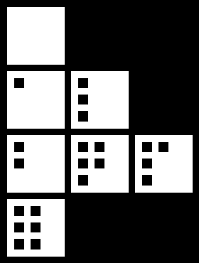

Now, I haven’t actually looked into the exact ins and outs of d-touch, but from my testing these markers do seem to actually work, which is great.
Having modified the code several (hundred) times, I’ve decided that ultimately, it needs to ask how many markers are required and handle the rest itself. It would work out the squarest, most skew-resistant marker it could, using the least empty space. This will require it to shape and position the white regions. The code in the current form can either generate correct filenames xor generate markers where dimensions are kept nice.
As an additional lump of code, this batch file will rename the files to their IDs without re-running the perl script. GeSHi apparently doesn’t like delayed expansion in batch files so it isn’t syntax highlighted because it breaks the HTML.
@echo off
SetLocal EnableDelayedExpansion

set _op=copy
set _from=markers
set _to=markersbyid
set _seq=seq.txt
set _newprefix=marker_

if not exist "%_to%" mkdir "%_to%"

set _LineNo=0
for /F "Tokens=* Eol=" %%i in (%_seq%) do (
set _tmp=%%i
%_op% "%_from%\image_!_tmp:,=-!.png" "%_to%\%_newprefix%!_LineNo!.png"
set /A _LineNo+=1
)